Analysis of Laser Marking Performance on Various Non-Ferrous Metals
Abstract
Laser marking for traceability on metal surfaces has become a significant new requirement for producers. The technology was introduced to the aluminum sector a few years ago. Other non-ferrous metal producers are now demanding it as well. As with aluminum, through careful control of surface roughness, high contrast identifiers can be etched onto the surface of other non-ferrous metals. High rms absorbing regions, or low rms reflective regions can be created, resulting in dark or bright marks respectively. Zinc, lead, magnesium, titanium, nickel, tin and aluminum were all successfully marked. High contrast marks for barcodes, 2D codes and serial numbers were created. These marks can be used to ensure permanent traceability of metal products. For each metal, marking time and contrast levels were studied, and optimal marking parameters determined. An interesting comparison resulted.
Introduction
Laser technology has proven to be an efficient way to produce identifiers on aluminum [1] by changing the reflective properties of the surface in a very selective way [2]. It is fast and can produce high contrast and permanent marks. The utility of aluminum no longer needs to be proven. With characteristics such as resistance to oxidation, low density or malleability, laser marking can be used in many industries, including transportation, building & construction, packaging, consumer goods, electronics, and many more. However, aluminum is only one of the many metals used in these industries. For this study, laser marking of different non-ferrous metals were analyzed. A selection of 6 different metals was made, each having different applications: lead, tin, zinc, magnesium, titanium and nickel. The laser marking performances of these materials were compared to results previously obtained with aluminum.
Lead is a heavy, but rather soft and weak material with a low melting temperature. It is used, for example, for x-ray shields and storage batteries.
Tin has similar physical properties to lead and is often used to coat other metals to prevent corrosion (steel for tin cans, for example, where it inhibits chemical reactions with food).
Zinc is also relatively soft. It is mainly used for protection against corrosion, but can also be found in alloyed forms for non-structural castings with requirements for very thin walls and smooth surfaces (e.g. toy cars).
Magnesium has the lowest density of the metals studied. This metal is used in applications where weight is a limitation, such as aircraft and automotive components. Magnesium alloys containing aluminium, zinc or manganese are found in steering wheels, cockpit carriers, automotive transmission cases and laptop computers, cellular phones and TV sets.
Titanium is extremely strong metal and relatively light weight. At normal temperature, it has good corrosion resistance. Titanium-based alloys are used for airplane structures, space vehicles, surgical implants and more, making it one of the most relevant metals for our study of industrial metals.
Nickel is highly resistant to corrosion (particularly in basic environments) and ferromagnetic (at room temperature), and has low thermal conductivity. Its main application is as an alloying element, for example in iron and steels, non-ferrous metals like aluminum or super alloys. It is also often electroplated on other material as a protection against corrosion [3].
This study shows the results of laser marking of these non-ferrous metals (unalloyed and at room temperature). A rigorous analysis of the influence of the parameters on the marks was conducted. The level of contrast as a function of marking time was determined for each metal, and led to an interesting comparison of marking performance between them.
Experiment
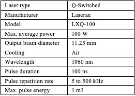
The experiment was performed with a 100W pulsed fiber laser marking system operating at 1.06 μm. Detailed laser characteristics are shown in Table 1.
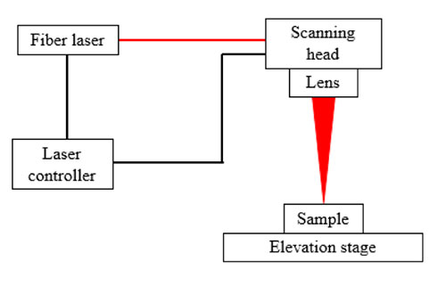
The 11.25 mm beam was focused on the surface by a 420mm focal length lens as shown on Figure 1, where the experimental setup is detailed. This resulted in a spot size of approximately 90 µm on the target sample.
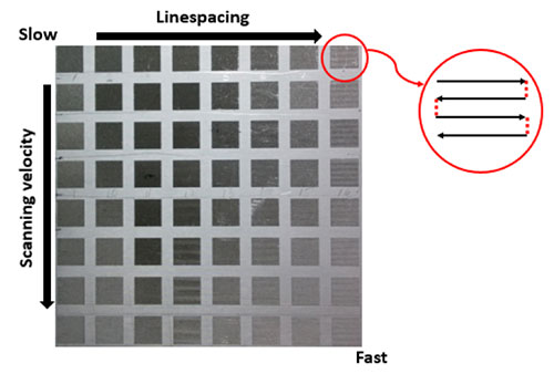
In order to find the optimum laser parameters for high contrast at high speed, matrices of squares were marked using different sets of parameters. As shown in Figure 2, each square was made using a series of lines (black arrow) separated by a fixed line spacing (red dotted line), both shown in the circle of figure 2. The matrices were produced by changing the line spacing within the same row, and the scanning velocity within the same column. This resulted in the slowest regime being at the upper left portion of the matrix and the fastest regime at the bottom right.
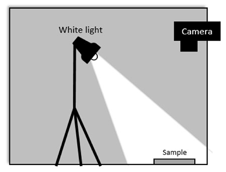
To find the best parameter set for fast and high contrast marking, first several matrices were marked. Different pulse energies were used to find the most suitable energy level for each material under investigation. Upon selecting the appropriate pulse energy, the scanning velocity and the line spacing were optimized. To increase contrast, a white background was marked behind the matrix. The parameters for marking this white background had been previously optimized using a similar method. To evaluate contrast, photographs of the samples were analyzed using an algorithm developed under MATLAB (matrix laboratory). The photographs were taken under white light illumination in an enclosed area, to eliminate ambient light, as shown in Figure 3. The contrast was defined as the difference between the grey scale level of the white background and the grey scale level of the black mark. (Perfect white has a “grey level” of 255 and perfect black has a “grey level” of 0). This analysis made it possible to accurately compare the marks made on different materials.
Results
Figure 4 shows the best contrast obtained for each material. Different colorations can be observed in the blackened portions, especially for tin and nickel. For this reason, the images for the numerical analysis were converted to grayscale values.
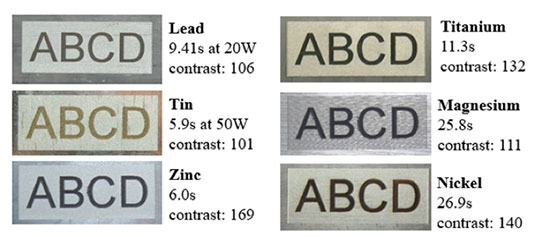
Photographs perpendicular to the metal surface of each material were taken. An attempt to optimize lighting for the best possible contrast (near laboratory conditions) was not made. It was felt that reproducing lighting found in a typical manufacturing environment was more relevant. (It might be argued that more stringent lighting criteria might be useful, but would also be more difficult to establish and maintain, and with minimal added benefit.)
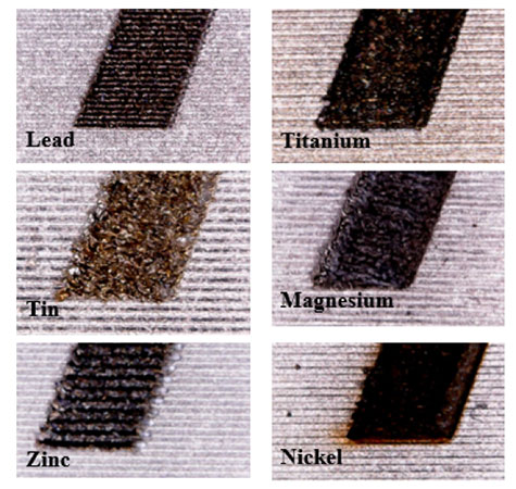
Titanium, zinc and nickel all demonstrated similar contrast levels (between 132 and 145) while lead, tin and magnesium had optimal contrast at levels between 101 and 111. All these contrast levels were sufficient for easy reading of alphanumeric codes, barcodes or 2D codes. Although maximum contrasts were lower for lead and tin, they were reached where greater marking speeds were used. By looking at the microscopic image of the marks on the different materials, it was observed that the surface morphology differs among them (see Figure 5). Sometimes the most efficient way to produce black marks is by producing well-defined deep lines with wide line spacings, as with lead and zinc. For other materials, it was not possible to obtain this morphology. The best results for titanium, tin, magnesium and nickel were obtained with narrower line spacing, where the surface was melted in a more random manner.
Because cycle time is often critical for industrial applications, the parameters providing the maximum contrast may not always be the most suitable ones for a given application. In fact, most of the time the process can be sped up when insufficient contrast is obtained. Figure 6 shows the curves of the best contrast achieved as a function of the marking speed, using an average laser power of 100 W.
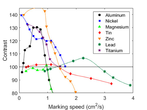
In general, contrast decreases (after a certain point) with increased marking speed. This is understandable since less energy was delivered to the surface. Each curve generated was different, in the sense that the same optimal contrast was not reached and did not decrease at the same rate. The curves of nickel, zinc and titanium started with high contrast, rapidly decreasing with increased marking speed.
The contrast achieved on tin and lead was almost stable for the full range of marking speeds tested.
The contrast for the magnesium stayed at around 100 up to about approximately 1 cm2/s and then dropped rapidly.
For aluminum and lead, a clear optimal parameter set was observed, which was not clearly the case for the other metals.
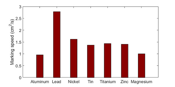
The histogram in Figure 6 shows the maximum marking speed that resulted in a contrast level of 100, more than enough for most applications. It corresponded to the maximum marking speed where the curves in figure 5 cross the horizontal line.
Aluminum has the lowest marking speed (0.96 cm2/s) and lead has the highest marking speed (2.79 cm2/s).
For the other metals, marking speeds varied between 1.00 cm2/s and 1.62 cm2/s.
Conclusion
This study showed that high contrast marks can be achieved on lead, nickel, tin, titanium, zinc and magnesium at marking speeds similar or even higher than those typically used for aluminum. This paves the way to the integration of laser marking systems in these industries, where traceability of material and components are often (becoming) of equal importance. The higher efficiency compared to aluminum marking will facilitate the introduction of laser marking because of the lower laser power necessary, making these projects even more affordable. Marking in most primary metal industries and many metal processing industries requires marking on hot material. A study of the optimal laser marking parameters for these metals at high temperatures could be interesting. Marking speeds would be expected to be even higher at higher temperatures as demonstrated previously for aluminum [1]. The impact of alloying elements could also be of interest for further investigations. In aluminum it was demonstrated that hardening elements (like Si) actually had a positive effect on readability and contrast of marks and permitted increased marking speeds compared to pure (primary) metal.
References
1) Fraser, A., Brochu, V., Gingras, D., & Godmaire, X. P., Important considerations for laser marking an identifier on aluminum. In Light Metals 2016 (pp. 261-264). Springer International Publishing.
2) Maltais, J., Brochu, V., Frayssinous, C., Vallée, R., Godmaire, X. and Fraser, A., Surface analysis study of laser marking of aluminum, Proceedings of ICSOBA 2016
3) Callister, W. D., & Rethwisch, D. G. (2011). Materials science and engineering (Vol. 5). NY: John Wiley & Sons.