Important Consideration for Laser Marking an Identifier on Die Casting Parts
Abstract
Traceability and individual part marking of castings is becoming increasingly important. Different marking technologies are available and have been presented and discussed in the previous paper (NADCA 2016). For die casting in most cases laser marking is clearly the most suitable technology - and sometimes actually the only viable and/or long term most economical one. This is due to the fast cycle time; harsh environment (lubricants and dust on parts, and their high temperature when marked); heat treatment and/or subsequent surface treatments (like shot blasting, e-coating, painting, etc.) of the parts which the marking needs to survive and remain readable not only for the human eye but also for automatic 2D bar code readers (otherwise a perfectly good casting has to be scrapped); and the often complex 3D shapes to be marked. Part marking should never be the bottleneck in the process or a contributor to scrap rate due to unreadable markings. And it is not just any laser marker that is capable of doing this complex job. It requires a dedicated system tuned for the specific application and process. In this paper we present and discuss laser safety (often a concern), and how a system might be designed and developed that is easy to install while guaranteeing Class 1 laser safety in any typical die casting environment. We also show the results of extensive research work that has been done since last year’s paper and the successful development of a completely suitable laser marking system for die casting, including pre-engineered solutions for easy retrofitting into existing die casting cells.
Introduction
Direct part marking is a way to trace parts throughout the whole process of production and after in the use phase of the product. This practice is becoming a necessity in the die casting industry – as it is in many others. There are some challenges associated with the environment and the processes undergone by die castings. This includes short cycle time, surfaces that are not (perfectly) flat, high temperature, abrasive post-treatment. In a previous study, we presented several technologies used to identify parts [1]. The laser marking technology proved to meet these numerous criteria. To mark an identifier on metal, we use the high energy of a pulse fiber laser in the infrared, which is absorbed by the surface. This way we can reach the minimum degradation energy threshold of the material and modify its surface and the way it is reflecting the ambient light to create high contrast marking. The laser is computer controlled and it is possible to mark anything effortlessly, for example a serial number, 2D barcode, 1D barcode, logo and more. Moreover, the marking time depends among other things on the average power of the laser, so it is possible to adapt the laser power to respect the cycle time while minimizing the cost of the solution.
In this paper, we present some of the important aspects about the integration of a laser marking system for traceability, with focus on laser safety. The integration of a Class 4 laser as a Class 1 laser system is presented. Two different approaches are explained: The open air enclosure and the sealed enclosure. Both of these approaches can ensure Class 1 operation and thus 100% safety for the operators. Other process related aspects are also presented along with their impact on the marking quality. In the second part of the paper, we discuss the influence of some laser parameters on the readability of laser marked Data Matrix on two very different but both very challenging post treatments: E-coating and shot blast.
Integration of laser marking system in die casting environment
Integration of a laser marking machine in a die casting environment requires considering important aspects such as the repeatability of the exact position of the part surface to be marked, the cycle time of the process and the size and composition of the identifier to be marked. In some applications where 100% “bulletproof traceability” is needed, it is recommended to also use a camera to read and confirm the exact marked code. On top of that, it is essential to correctly consider the health and safety aspects of a Class IV laser integration.
Positioning repeatability
An important aspect of the laser marking process is the focusing of the light on the surface through the focusing lens. In order to make a high contrast mark on aluminum, the focus position should be within ± 3 mm from the material surface if using a 2D head. Figure 1 shows the results of marking for different surface positions across the focus region (dimensions in mm).
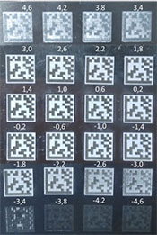
Looking at Figure 1, we see that as long as the surface position is within a certain position range from the focus position, almost no visible changes are seen in the marking quality and contrast. However, right outside the limit of that range, the marking quality and contrast drastically decreases to zero. This is explained by the fact that the marking process requires a minimum intensity threshold to be visible.
If the part surface cannot be repeatably placed within that range because of part shape distortion, non-repeatable part gripping or any other reason, a so-called 3D head is required. In this case, distance measurement sensors are used to measure the part surface position and transfer the information to the 3D head controller. The communication between the distance measurement sensor and the laser system will then ensure a dynamic compensation of the surface positioning variation, with a delay of less than 50 ms added.
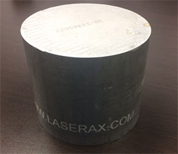
The 3D head also has the capability to mark on a 3D shape, i.e. shape where the distance from the surface to the laser varies within the identifier area. Figure 2 below shows a laser marked identifier on a 3D surface done with a 3D head.
Cycle time vs size and composition of the identifier to mark
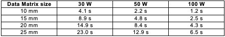
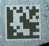
The size and composition of the identifier is directly linked to the time required to perform the marking. Table 1 below shows an experimentally developed timing rule of thumb for marking high contrast square 2D codes (of given side lengths) on aluminum, considering no post treatments are needed. An example of the corresponding contrast is shown in figure 3.
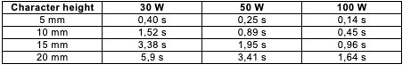
As it is adding black area, marking alphanumeric characters under the code will also add some time to the process. The height and the width of these characters will then have an important effect on the overall time for marking so it is important to adjust them based on the real needs. Table 2 shows typical marking time per character (in Arial or similar) depending on the height of the character and the laser power.
Camera reading and confirmation
To ensure fully “bulletproof traceability”, a camera reading of the code and a comparison with the data to be marked may be very useful. If the part is successfully read and compared positively to the requested mark the traceability on that part can be 100% certified. Also, as code marking often includes strict rules on quality, the camera reading step will ensure that the marked codes respect the quality criteria specified by the manufacturer or the customer.
Laser mark identifiers on aluminum have excellent grading values when they are not altered by any post process. However, most post processes, and particularly shot blast, will have the effect of decreasing the grading of the mark (decrease in quality after the process). Nevertheless, for the shot blast parameters that we tried with Mercury Marine, with the appropriately chosen set of laser parameters, it is possible to read the code after shot blast, as we explain in detail in the following sections.
Laser safety
The 1.06 µm fiber laser wavelength is within the 0.4 µm – 1.4 µm wavelength range considered the “danger zone” for the human retina. To ensure the affected personnel is appropriately protected, it is strongly recommended to integrate the laser marking system inside a Class 1 laser machine. The ANSI 1040.10 is the standard that applies in the United States while the IEC 60825-1 is the one for Canada and Europe. In addition, in the US, the integrator must register the final laser machine with the FDA through the CDRH (Center for Devices and Radiological Health).
Although there are multiple ways to integrate a laser in an industrial environment, the two methods described in this section are well suited for die casting: The open air enclosure with limited access, and the sealed enclosure with turntable.
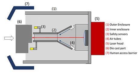
The ‘open-air’ safety enclosure is shown in Figure 5 above. The enclosure is actually made of three separate enclosures: An outer one [Fig.5 (1)], an inner one [Fig.5 (2)] and a human access barrier [Fig.5 (7)]. These three barriers/enclosures used together are necessary to assure laser safety and respect the ANSI 1040.1 standard. The inner enclosure’s purpose is to decrease the angle range through which the beam could potentially be reflected after an unanticipated reflection. Considering the part geometry and the gap between the part and the inner enclosure (which is ensured by the use of two proximity sensors), the possible paths of dangerous rays are shown in red in Figure 6.
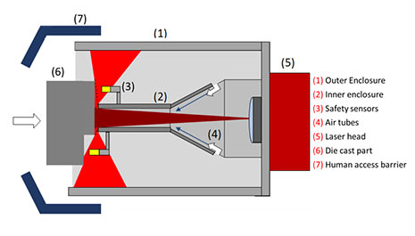
The purpose of the outer enclosure is to block these rays from coming out as specular rays, which are dangerous over several tens of meters/yards. This enclosure must be made of absorptive and diffusive material such as black anodized aluminum or black painted steel. The reflection of the incoming laser light inside this enclosure will be scattered in all directions, greatly reducing the danger zone emerging from the inner enclosure. This danger zone is shown in orange in Figure 7. It can have a maximum radius of 80 cm for the LXQ-100 (100W) and 36 cm for the LXQ-20 (20W).
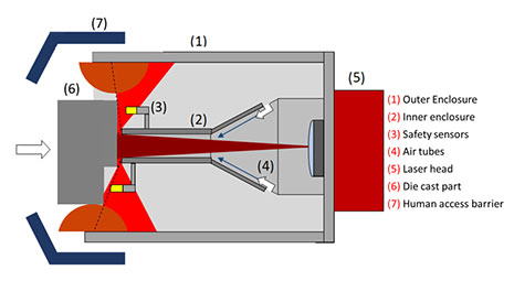
The third part of the enclosure, the human access barrier, ensures that no human can get access to the remaining danger zone when the machine is in operation. Although procedural safety means are already installed to limit access to the cell while it is in operation, these procedures are not acceptable under the ANSI 1040.10 standard that requires engineering means to prevent human access to radiation above the intensity limit of the standard, which is 5 mW/cm2 for the 1064 nm wavelength and the 100 ns pulse duration of the LXQ laser series. These engineering means can be a physical barrier as proposed, but could also be a zone scanning tool or a sensing mat. If a physical barrier is possible, it is preferred. Otherwise another engineering means should be employed.
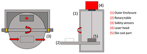
The sealed enclosure designed and presented in this section includes a rotary loading table that allows the robot or operator to load and unload the part in the machine while the laser is marking the part. Figure 8 shows the principle of operation of this enclosure design. The part is first loaded on a piece holder designed specifically for the part geometry. Then the table turns, locating the part within the enclosure. While this part is being laser marked, the robot can continue to work on the rest of the sequence; moving through quenching, trimming, placing the part on exit conveyor, grabbing the next part, and verification of the mark’s integrity. Safety sensors are used to ensure the door remains closed during the laser marking process. To be a valid Class 1 laser machine, this type of enclosure must have no holes or gaps that would allow a direct or specularly reflected beam to emerge.
This type of enclosure is especially interesting for manufacturers because the table can be loaded and unloaded while marking occurs. That makes the time for the table to revolve the only time to consider as a non hidden-time process, provided the marking time is less than the rest of the cycle time to mark two parts. This type of enclosure thus makes it possible to use much longer marking times, such as those required for deep shot blast resistant marks, presented in the next section about post treatments.
Comparison between the two enclosure types
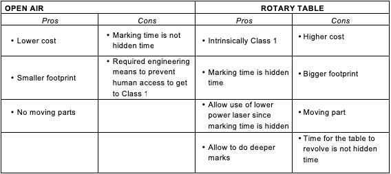
Although the two enclosure types presented above can be well suited for a die casting environment, they have their own advantages and disadvantages. Table 3 below summarizes the pros and cons of these two types of industrial enclosures.
Post treatment resistance study
A Laserax LXQ-100 (100W) fiber laser was used to mark 2D Data Matrix code on a Mercury Marine aluminum part made of a 362 alloy (a low iron, high silicon alloy). This laser operates at a wavelength of 1.06μm and emits pulses of 100 ns duration at a frequency of 100 kHz, for an average power of 100W. The readability is then studied after having undergone several post-treatments: E coating only, shot blasting only, and shot blasting and E-coating.
The study focuses on the influence of laser parameters on the robustness of these markings to determine the optimal parameters for each process. For shot blasting, the technique of deep marking is used [1]. It consists in protecting the mark from the shot blast process by lowering the surface on which the black is marked. To do so, multiple passes are done with the laser to remove material before doing the blackening. If the cells are small enough, shot will not be able to reach the black marking and it will remain intact. Surface markings will also be tested and compared to deep ones. Those ones would be advantageous compared to the previous method since it is much faster to mark without the deep etching step. Although a multitude of parameters can affect the results, this study focuses on the following:
Cell Size
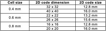
For the deep-marked 2D barcode, two different code sizes were used, approximately 13 mm and 16 mm and three cell sizes were tested: 0.4 mm, 0.6 mm and 0.8 mm. The number of cells was adjusted so that the total size was approximately 13 mm or 16 mm. Smaller cells allowed encoding more information and thus increased the redundancy in the encoding of the 2D code information. On the other hand, larger cells are easier to read. It was therefore necessary to find the right balance between the size of the cells and the amount of redundancy. The table below summarizes the dimensions of the marking samples.
To mark deep into the material, it was necessary to make several passes with the laser before marking the code itself. Material was etched so that the marking that was in the bottom was then protected by the surface around it. The depth and the time of marking was increased with the number of passes. For surface markings, the number of passes is one.
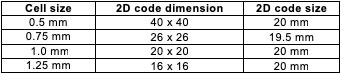
For surface marked 2D code (no deep etching step), a larger dimension of 20mm x 20mm was used since these “standard” marks are much faster to make. Cell sizes from 0.5mm to 1.25mm were tested. The corresponding Data Matrix dimensions is presented in the following table.
For standard applications, a white background provides better contrast and better readability. Since the post-processes we studied modified the surface, it was not obvious if this was needed. For the resistance to shot blast, white background will not be tested because it has been shown in a previous study that it was erased by the process. For e-coating, all samples were done twice, both with and without white backgrounds, to study the effect of backgrounds on readability.
Results
The results are divided in three sections: Painting only, shot blasting only, shot blasting and painting. The data was collected with a Cognex Dataman 8050 reader. Each sample was read six times, with different orientations. It then collected the value of the contrast and the unused error. The contrast was a value between 0 and 1 defining the brightness difference between the dark and pale part of the bar code. A contrast closest to 1 is desired. The unused error is a value between 0 and 100. It represents the amount of error correction that was needed to read the code. An unused error of 100 means that no error correction was needed and therefore the code was not damaged at all. An unused error of more than 75 is considered satisfactory.
Painting Only
After the painting process, it became clear that the cell size was very important for the readability of the Data Matrix. Of the four dimensions that were tested, only two resulted in 2D codes that were readable. Those with cell sizes of 0.5 mm and 0.75 mm were not readable regardless of the parameters used. This means that cell sizes of 0.75 mm and below is not suitable for this application. The influence of the marking parameters on the resistance to painting of the codes was also investigated. Two different marking speeds and three different line-spacings were studied. Each combination gave enough contrast to result in good readability. We did not see a significant difference between results, so the fastest parameters should be selected. In figure 10a and 10b, we can see a picture of the code after painting, with and without a white background, respectively.

The parameters presented in table 5 were determined to be the best for resistance to E-coating. This was done without a white background. In addition to being the fastest set of parameters, it also showed a good visual aspect (figure 10b), a good contrast and was readable from six different angles. The unused error value of these marks is 100, so no error correction was necessary to read the code. As these parameters are standard parameters for marking on aluminum, it was also possible to read the code before the process of e-coat painting. Laser marking is then an effective solution for identification of parts in the die cast industry that have e-coating process in their production line.
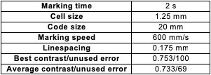
Figure 11 shows pictures of the same barcode taken from different angles. In both cases the contrast is high, but for the second situation the barcode is white while the background is black. This does not influence the readability of the code, since unlike the 1D code, only a difference in gray level is required without giving importance to which element is which color. This shows that the angle at which the camera is located with respect to the illumination has a great impact on the observed result.

Shot blast only
Shot blast is an abrasive treatment that changes the roughness of the surface. To resist these kinds of treatment, much deeper codes must be marked. A “deep marking” technique, described below, is therefore used.
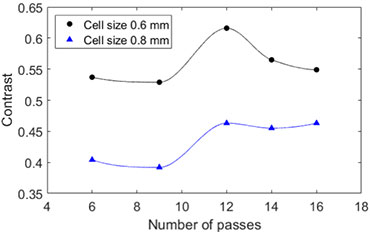
The individual cell size is an important factor influencing the readability of the 2D code after shot blasting. The marks done with 0.4 mm cells were not readable after the shot blast treatment while the 0.6 mm and 0.8 mm show very good results. Figure 12 presents the evolution of the contrast with respect to the number of etching passes for the 0.6 mm and 0.8 mm cell sizes. We saw a higher drop of contrast for the 0.8 mm than for the 0.6 mm cell size code. We think this is due to the fact that the bottom of the etched cases, where the black marking is located, is more exposed to the shot in the process. The optimal cell size seems to be 0.6 mm since at 0.4 mm they are not readable and at 0.8 mm contrast is lost. Note that the average contrast before the shot blast process was 0.61, so the contrast drop due to the shot blast process is only in the order of 10% or less.
The cycle time is dependent on the depth of marking. As we can see in figure 12, it is not necessary to mark deeply. In fact, there is a depth beyond which the marking is protected. It was observed that the fastest mark, with three laser passes, was not deep enough. It was completely erased and therefore not readable. After 6 passes, these marks became readable, but a substantial amount of error correction was needed. With 9 passes good results were achieved, both in contrast and unused correction error. With 12 passes, the contrast reaches a maximum which is very close to the average contrast of 0.61 measured before the shot blast process. For the 6 different reading angles, the contrast varies between 0.525 and 0.616 while the unused error is between 10 and 90. With these parameters, it takes 37 seconds to mark a 12.3mm Data Matrix with the 100W laser. Such a code has a data capacity of 60 numeric characters or 43 alphanumeric characters.
The technique of deep marking can produce 2D codes resistant to shot blasting but requires a relatively high cycle time. Some applications may not allow such a long cycle time and part marking should never be the bottleneck in the process.
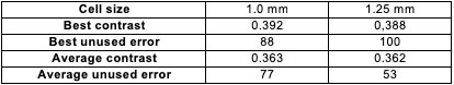
In order to reduce marking time, we also tested the resistance of surface marking to shot blasting. Codes with 0.75 mm, 1.0 mm and 1.25 mm cell size were tested. Since shot blasting is an abrasive process, the surface marks will be affected and therefore their contrast and readability will be different. As with deep marking, the cell size influenced the results: Similar to the mark submitted to E-coating, cells of 0.75 mm were not readable. For the 1 mm and 1.25 mm cell sizes, the best and average results over six measurements are presented in table 6. The average contrast value before the post process was 0.72. The quality of the mark was sufficient for the reader to read it from the 6 different angles tested. But, as we expected, the contrast was low because the code was not protected unlike the one with the “deep” mark. If less contrast is acceptable, this method may be a good alternative to deep marking if a shorter cycle time is necessary. Note that the images showing the results after shot blast were accidentally not saved correctly and we could not re-photograph them because the painting was already done, so we unfortunately cannot show them in this paper.
Shot Blat and Painting
After being shot blasted, the shot blasted samples undergo the E-coating process. The paint changed the appearance of the mark, so the readability was different. Figure 13 shows the evolution of the contrast through the sequence of post processes, for the optimal 0.6 mm cell size. Note the drop in contrast after shot blasting. However, the application of E-coat paint on the sample increased the contrast to even higher levels than before either post process. E-coating then, is a way to considerably increase the contrast of marking after shot blast.

Figure 14 presents pictures of the 2D codes and shows the number of passes and required marking time for each.
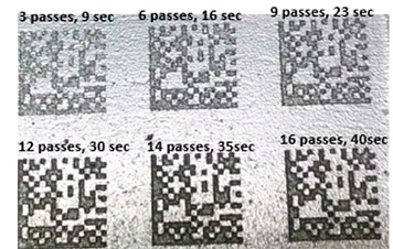
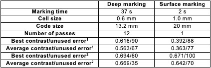
Table 7 presents a summary of the best results for deep marking and surface marking, for the process of shot blast only and shot blast + painted.
Conclusion
Laser marking is the most viable, and sometimes the only possible technology for permanently marking die castings to ensure traceability of the component from casting to final assembly and even in the use phase. While there are many off the shelf laser markers on the market, it requires a significant amount of know-how to select the right technology, adjust all the parameters, determine the exact marking procedure and marking type as well as the integration of a laser marker into a die casting cell in a way that Class 1 laser safety can be guaranteed. The laser type and marking parameters need to be adjusted to provide the required marking in the given cycle time and setup/environment, and often the marking needs to be adjusted to guarantee proper readability after surface treatment processes – and often the right compromise needs to be found between cycle time, required contrast and size of the marking. Even for shot blasting and e-coating, certainly the two most demanding surface treatments for die casting, solutions can be found so that the markings will remain readable and a second marking step or possible loss of traceability can be avoided. If the part positioning is not perfectly repeatable, a 3D head can identify the position and adjust the laser accordingly. A subsequent immediate verification of the marking with a camera can in some cases be a useful addition. Compared to other marking technologies, laser marking is often considered as rather dangerous, but it was shown that there are several possible ways of building and integrating a laser marker into any kind of die casting cell (or any other manufacturing environment) in a very safe way that guarantees Class 1 laser safety and will ensure that no operator will be put at any kind of unreasonable safety risk. With this paper we hope to have addressed some of the major concerns of die casters when it comes to laser marking. We have been working on providing solutions for this industry for several years and feel that we are now in a position to help die casters manage the challenges of their processes and environment and enable perfect traceability that will help them with quality assurance, improve their processes, and satisfy customer requirements.
References
1. Fraser, A., Maltais, J., Hartlieb, M., Frayssinous, C., Vallée, R., Godmaire, X., “Review of technologies for identification of die casting parts,” NADCA Transactions 2016