Laser Marking and 3D Imaging of Aluminum Products
Abstract
Most industrial products have (challenging) 3D shapes, many of them require traceability and individual marking. Although some laser marking systems on the market have 3D capabilities, they require the 3D shape to be loaded in the laser controller and the part to be precisely located. However, many industrial processes requiring direct part identification cannot fulfill those precise positioning requirements. To overcome these limitations, a 3D laser marker with integrated 3D imaging system was developed. This imaging system obtains the 3D image of the piece, and then the laser controller starts the marking process so that the focus fits on the part surface. The whole 3D data acquisition and transfer takes less than 3 seconds. This solves the problem of part positioning and simplifies the integration, while also providing 3D data of the surface that can be used for quality control.
Introduction
As traceability and process control are becoming more and more important, not only in a growing number of industries, but also much wider spread across the value chain, often starting with the raw material, marking technologies are increasingly challenged by ever increasing requirements of customers in the metal production and processing industries. Many different part marking technologies have been developed and are being used in the industry, but of all the available ones the laser marking technology is clearly evolving now the fastest and is the only one capable of meeting today’s and tomorrow’s needs in terms of speed, ability to mark at a (variable) distance, uneven surface which is sometimes still hot and covered with lubricants or other contaminants. [1]
Galvo-based laser marking systems have been used for decades to mark identifiers on parts’ surfaces. They are in use in many industries, with growth being particularly strong in the medical, food and beverage industries. The right choice of laser type, wavelength and pulsed regime allows the achievement of good marking results on almost any material. Metals are typically marked with pulsed fiber or YAG lasers emitting at 1.06 µm. CO2 lasers at 10.6 µm (or also 10.2 µm and 9.6 µm) are mainly used for organic materials such as wood, cardboard, leather and fabric. Plastics can be marked with both laser types but better contrast is usually achieved at the 1.06 µm wavelength.
An important parameter of galvo-based laser marking systems is the lens focal length (FL). The shorter the FL is, the smaller the focused spot can be, thus increasing the laser intensity in order to reach the melting or ablation threshold required to efficiently mark the material. On the other hand, a shorter FL has a small working field and a small depth of focus. Working field is the area that the focused beam can reach, and it must be at least the size of the identifier to be laser marked, to avoid having to move the laser head. Depth of focus is the effective distance below and above the focal plane at which the laser process is still efficient.
Depth of focus is inherent to any laser marking process and must be taken into consideration when choosing the right laser marking system for a specific application. A typical 160 mm FL lens used to mark a black identifier on an aluminum surface has a depth of focus around ± 1.5 mm. Using a longer FL of 420 mm allows the beam to reach a depth of focus of ± 3 mm. However, many industrial products cannot achieve this positioning precision using standard manipulation tools.
In aluminum and iron/steel smelters, the positioning precisions achieved are far below these values. Typically, this is overcome by mounting the laser head on a motorized arm. The arm will position the head in order to maintain the desired distance from the surface. The distance offset can be obtained either from a distance sensor or a simple abutment device. However, these motorized arms can be costly, require additional floor space and increase the need for ongoing maintenance. Their movement may also increase the overall cycle time.
Another method to eliminate these issues may be to use a 3D galvo-based laser head. These heads, in addition to the two galvo-mounted moving mirrors, also have a galvo-driven moving lens. With this kind of system, it is possible to almost instantaneously change the position of the focal point without moving the head itself. An external command can be used to have the lens adjust its focal position through a signal provided by an external distance sensor. The offset generated could be well sufficient for applications where the surface to be marked is flat and always oriented perpendicular to the laser head.
Despite their different limitations and inconveniences, these existing solutions can be found in many industrial applications. But it was absolutely important to go one step further with the developments: An innovative laser marking system was developed that clearly helps overcome the different limitations and problems of the currently existing systems. It links a standard three axis galvo-based scan head with a 3D imaging system. This allows a mark to be applied to any surface (of any shape, type or temperature) positioned under the laser head – without the limitation of having to position it in a very precise way all the time.
Technology basis
Laserax’s LXQ 3D Vision laser marking technology is based on the existing Laserax LXQ 3D fiber laser marking system. This system is combined with a structured light pattern 3D imaging system. A Digital Light Processing (DLP) system is used to project structured light patterns on the part to be laser marked, while a camera, synchronized with the DLP, acquires the resulting images. The images are then processed through dedicated 3D reconstruction software which then generates a 3D surface model. This 3D surface data provides the laser marking system with the required information on the location and the shape of the surface to be marked. This allows the focus to be placed on the actual part surface. The automated and rapid data transfer between the 3D vision system and the laser marking system allows the LXQ 3D Vision to mark any surface located within its effective focus range. This eliminates the need to manually download the 3D shape to the laser controller. Also, since the imaging process is done within the coordinate system of the laser, the LXQ 3D Vision eliminates the need for the precise positioning of the piece to be marked with respect to the laser marking head.
The integrated high-resolution camera provides another very interesting capability to the LXQ 3D Vision: 1D/2D code reading and validation. The system includes a database where all the marked codes are stored, along with other interesting parameters such as the date and time of the marking, confirmation that the code is read, as well as its correspondence with the required data. Further to this, other quality control parameters can also be added to the data set, such as a rms value of the surface profile and grey level of the laser marked black identifier.
Another interesting capability of the LXQ 3D Vision is its ability to detect defects on the surface (or the part in general) and avoid marking the identifier where these defects are located. The system has an option to ensure that the surface beneath the identifier is free of defects, up to a certain user defined level, to prevent laser marking at this location. If the default region doesn’t fall within pre-defined criteria, either the operator is alarmed as the part is scrap, or the marking is automatically translated to the closest location that meets the criteria. In the case of castings for example it is possible – if the marking is placed on the overflow side – to detect incomplete mold/die fills, which in a fully automated process might make it to a later stage of the production process without detection. On parts with still acceptable surface defects according to the part specification (but such that could impact the readability of the marking), this can help to increase the readability percentage to a higher level – which can overall reduce the scrap rate for this part and avoid customer complaints related to the part marking. All surface data are dynamically available to use by OEMs or end users for quality control purposes.
Performances
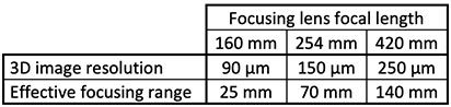
The 3D vision system included in the LXQ 3D Vision is capable of generating high resolution 3D images. The resolution provided depends on the optical configuration used. Three standard configurations are available and are defined by the focal length of the main focusing lens: 160 mm, 250 mm and 420 mm (other focal lengths are also available on request). The effective focusing range, i.e. the range of distance that provides an effective marking, is also dependent on the main focal length. These values are summarized in Table 1 below.
Most marking applications that use the 3D imaging system to compensate for bad or simply inconsistent positioning or for a curvy or tilted surface have resolution requirements far below the maximum resolution of the system. In these cases, the full resolution can be used for surface analysis and quality control while a lower resolution mapping is transferred to the laser marking system. This requires a typical time of three seconds between the beginning of the 3D imaging process and the beginning of the laser marking process. This is not only important in the production of sows or ingots, but especially particularly for parts produced e.g. by shape casting or forging processes and which are marked right after the first forming process in order to guarantee traceability throughout the entire value chain. These parts are characterized by often complex shapes, not always identical positioning e.g. on a conveyer belt, and very often short cycle times that require the marking to be equally fast (as it should never become the bottleneck in the production process).
The marking speed is directly proportional to the power level of the laser used. In order to meet the wide variety of market requirements, the LXQ 3D Vision marking system is available in power levels of 20W, 50W and 100W. With the 100W system, high contrast markings can be obtained at a marking speed as high as 0.6 cm2/s at 25 °C and over 1.2 cm2/s at 400 °C. With a giving power level the ultimate marking speed (for a specific given marking) is thus influenced by the temperature of the part to be marked. [2]
The LXQ 3D Vision marking system is equipped with a high definition camera that allows 1D and 2D codes (standard barcodes, QR code datamatrix) to be read. A large selection of code subtypes is also supported by the marking and reading systems.
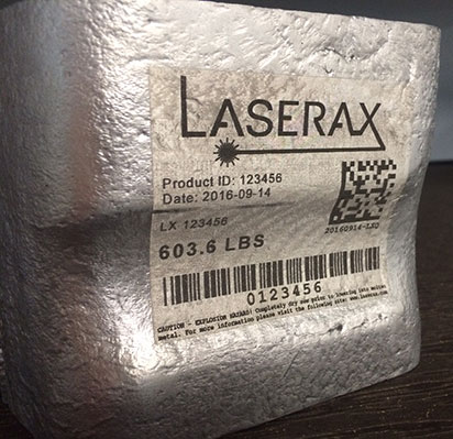
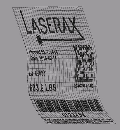
The Figure 1a and 1b show the marking of an ingot piece and the 3D surface generated showing the position of the identifier to be laser mark, respectively.
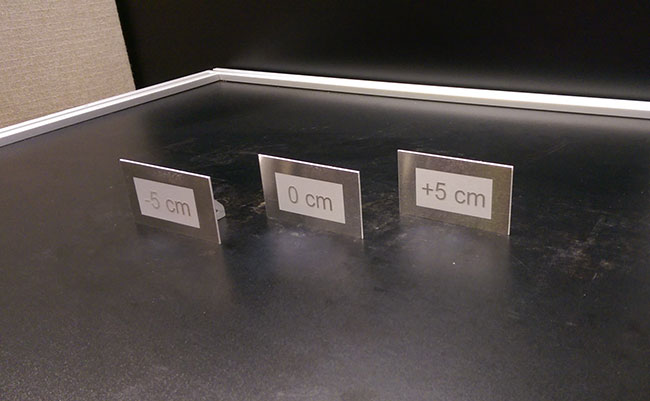
Another example of the capabilities of the LXQ3D vision is shown on the Figure 2. Laser marking has been applied to three aluminum plates located 5 cm apart from one another. The focus adjustment between each plate was automatically done by the measurement system that transfers the 3D data to the laser controller. This is a key enabler of the technology for marking parts “on the fly” without holding them down in a fixed position every time. In industrial environments this is a key feature e.g. for marking parts passing in front of the marking system on a conveyer. Laser marking is the only marking technology capable of this feature (which is simply impossible to achieve with inkjet, peen marking, etc.). [2]
Discussion
The first goal in coupling a 3D imaging system with our laser marking system was to offer an automatic focus adjustment to compensate for the lack of positioning precision achievable with massive metal pieces. This feature was at first requested by our customers for aluminum sow and large ingot laser marking. In the meantime, many more applications in the area of shape casting and forging have been identified that have identical or very similar requirements, often even more extreme. In shape casting often large parts are cast in automatic cells and they need to be marked immediately after casting while either on a conveyer (like sows or ingots) or held by a robot – in both cases repetitive precision in positioning the parts in front of a marking system would require significant investment in complex equipment, would slow down the cycle time, or would give other challenges very hard to overcome. In addition to meeting this need for auto focusing on a part in an imprecise location, the on-board camera allows other capabilities in addition to code reading, which could serve quality control needs. Such features have already been studied and are in the process of being developed.
Conclusion
The LXQ3D Vision system enables direct marking of parts (including with complex shapes) that are not precisely located with respect to the laser head. This greatly simplifies integration of the laser system for such applications by eliminating the need for motorized positioning of the laser head or by bringing the parts into the exact same position every time. The five-inch-wide range for effective marking of metal surfaces is sufficient to make that solution effective in e.g. most aluminum smelters marking applications, including sows, T-ingots and slabs. It is also a very important feature for shape casting, forging and other forming metal technologies with similar requirements. An additional advantage gained by using the system is that the part surface is analyzed and imperfections easily detected. If it is still in specification (and it is acceptable for the customer) the marking can simply be placed in a different spot that does not have the imperfection that would impact readability of the marking. In certain cases, this part scanning can even detect defective parts and therefore identify scrap at the earliest possible stage of the value chain, which avoids much higher losses of added value on a scrap part, or worse, having a scrap part finding its way to the customer! Combined with the high-speed laser marking capabilities of the LXQ-100 laser system, this solution is a very attractive technology which is now considered by many smelters and metal processing companies around the globe who want to improve the reliability of their traceability process and to decrease their operational costs related to part identification.
References
1. A. Fraser, J. Maltais, M. Hartlieb, C. Frayssinous, R.Vallée and X. P. Godmaire: Review of technologies for identification of die casting parts, NADCA Die Casting Congress proceedings 2016.
2. A. Fraser, V. Brochu, D. Gingras, X. Godmaire: Important considerations for laser marking an identifier on aluminum, Light metals 2016 (Proceedings of TMS 2016), p. 261-264