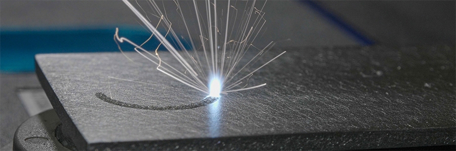
The Fastest Welding Process
When making cell-to-busbar connections, ultrasonic wire bonding typically takes between 500-1000ms per weld. Laser welding is much faster because it involves fewer, smoother mechanical movements: only ultra-fast mirrors located in the laser head need to be moved to position the laser beam. This drastically reduces the positioning time for each weld. When integrated with our robots, the average welding time including mechanical movements between cells can reach values under 100ms per cell.
| Cell Type | Busbar Thickness | Cell Thickness | Weld Type | Weld Dimension | Laser Power | Resistivity (µΩ) | Shear Test (N) | Time (ms) | Depth of Penetration (µm) |
|---|
| 21700 cylindrical | 250 µm Al 1100 | 500 µm nickel-plated steel | Positive Pole | Spiral 2.4 mm | 450W | 5 | 195 | 40 | 100-150 |
| 21700 cylindrical | 250 µm Al 1100 | 300 µm nickel-plated steel | Negative pole | S shape 3.6 x 0.5 mm | 450W | 5 | 150 | 40 | 100-150 |
| 4680 cylindrical | 600 µm Al 1050 | 0.8 mm Al 1100 | Positive Pole | Spiral 4 mm | 750W | 4 | 650 | 85 | 100-150 |
| 4680 cylindrical | 600 µm Al 1050 | 0.8 µm nickel-plated steel | Negative pole | Spiral 4 mm | 750W | 1.2 | 800 | 85 | 100-150 |
| Prismatic | 2 mm Al | 7 mm Al | AI Prismatic Pole | Donut 9.5 mm | Core: 3000W
Ring: 1500W | 3.5 | 1800 | 303 | 2000 |
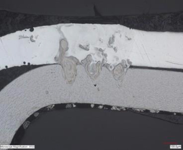
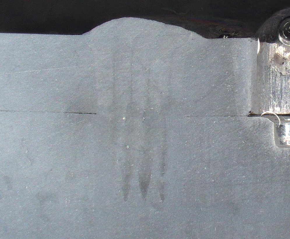
Cross-section view of busbar laser welding - Negative tab (Microscope image)
- 250 um Al on 300 um nickel-plated steel
- Shape: S Shape
- Pitch: 200 um
- Dimensions: 3.6 x 0.5 mm
- Speed: 500 mm/s
- No assist gas
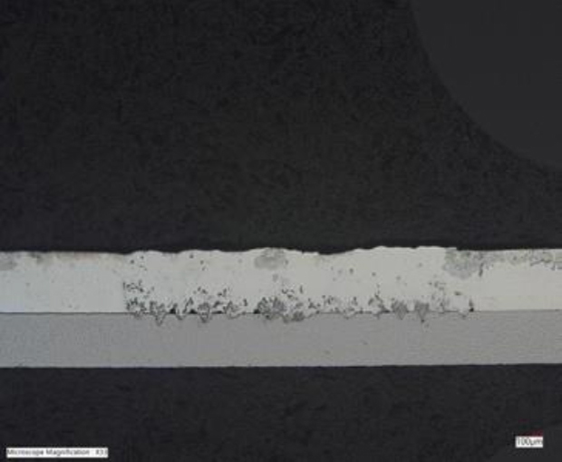
Cross-section view of busbar laser welding - Negative tab (Microscope image)
- 600 um Al on 500 um nickel-plated steel
- Shape: Spiral
- Pitch: 200 um
- Dimensions: 4mm
- Speed: 700 mm/s
- No assist gas
Cross-section view of busbar laser welding (SEM image)
- 2 mm Al on 3 mm Al terminal
- Shape: Donut Spiral
- Pitch: 350 μm
- Dimensions: 10 mm
- Speed: 1600 mm/s5 l/min Argon assist gas
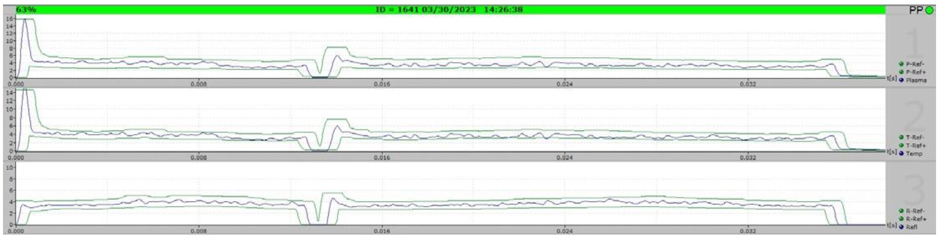
Real-time Weld Monitoring To Detect Bad Welds
Laser Weld Monitoring (LWM) devices can be used to detect bad welds in real time during laser welding. This ensures that every single weld in the battery is good, and that defective ones are reworked right away.
Optical sensors installed in the laser use reflected and emitted radiation from the weld to determine if the weld is good. They can detect different types of weld defects such as gap or contamination.
- Each row represents a wavelength that’s tracked by the LWM (plasma, heat, laser back reflection)
- The blue line in each row represents the radiated reflected light signals tracked in real time for the current weld
- The two green lines in each row represent the ± acceptance limits for the wavelength at any given time
- Blue lines that extend beyond the green acceptance limits for a certain period of time can be associated with weld defects
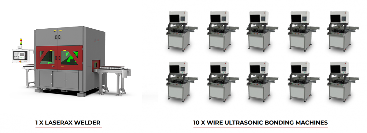
Revolutionizing Efficiency
Because of our faster welding speed, a single laser welding machine can easily work like 10 ultrasonic wire bonders. This minimizes the number of machines needed in production facilities, allowing you to:
- Save square footage
- Save energy
- Reduce maintenance
Cylindrical Cells: From 4 Welds To 2 Welds
Whereas ultrasonic wire bonding typically requires 4 welds per cell, laser welding only needs 2. This provides several benefits:
- A larger contact area
- Half as many potential failure points
- One weld carries all the current (higher current per weld)
- Less mechanical stress transferred to the module
- Smaller resistance (lower heat & electrical loss)
- Better current distribution
- Better heat transfer from cells to busbar conductors
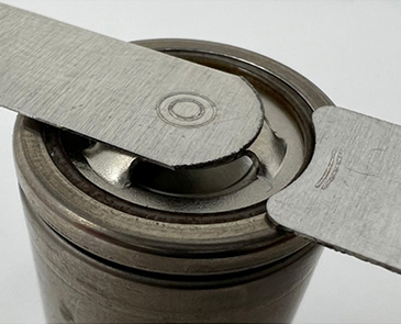
2 welds per cell (customizable weld pattern)
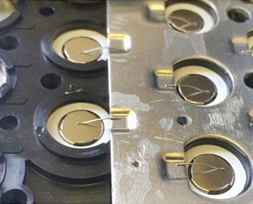
Ultrasonic wirebonding with 2 wires per cell (over and under) and 2 small welds