The goal of every electric vehicle manufacturer is to make electric motors more efficient, which means spending less energy for motion and designing smaller batteries with optimal thermal management.
When it comes to transferring power from the batteries to the wheels of an electric vehicle, the rotor is one of the key elements. Its manufacturing process can be optimized in several ways for a more efficient e-motor.
The rotor manufacturing process can be divided into 6 steps:
The rotor’s design depends on the materials used and the engineering requirements. In induction motors, for example, the rotor generates a magnetic field with the stator. For this reason, magnetic materials such as cobalt, nickel, and iron are used. The cost, strength, and availability of these materials strongly influence the design.
These requirements and challenges are addressed during the design and prototype phase. Take for example the integration of magnets inside the rotor (interior permanent magnets). The design of the rotor’s laminations needs to take into consideration that some space is required for the magnets and that the magnetic field path needs to be optimized.
Once the design is complete and the prototype is assembled, it is placed on a test bench. This equipment measures performance indicators such as torque curve, rpm per volt, resistance, and impedance levels to ensure that they meet requirements expected of an AC motor (alternating current). The rotor’s balance is also checked as if it were a final inspection before e-motor assembly (more on this step in Impregnation and Balancing).
Here is an example of a rotor bench test that can be used for prototypes and final products.
2. Lamination
An automated rotor and stator stamping machine.
The rotor’s core is made of hundreds of small slices of metallic material called laminations. Each is stamped or punched and then thinly coated (a few microns) to protect from corrosion and provide better insulation.
This production process called lamination begins when all laminations are stacked one above the other and then stamped to create the rotor’s core with the help of a hydraulic stamping press. This manufacturing method is essential to build an efficient rotor: laminations reduce eddy current inside the rotor while increasing the rotor’s strength and improving its balance.
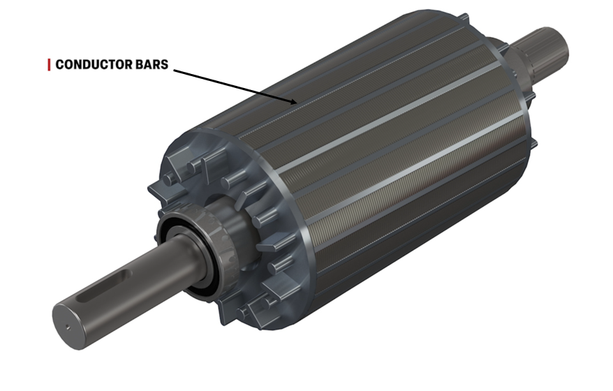
3. Magnets or Conductor Bars Insertion
The rotor contributes to generating a magnetic field along with the stator. To do so, magnetic elements are installed in the rotor. Those can be magnets, conductor bars, or copper windings.
The most common approach in recent electric vehicles is to use interior permanent magnets (IPM) inside the laminations. This type of rotor can run at a higher rpm without raising the centrifugal force, is further away from heat sources, and generates a more concentrated magnetic field for better performance. On high performance electric motors, a carbon wrap is installed around the rotor to improve its strength and increase the maximum rpm and power.
In the following video, you can see magnets inside a rotor’s core.
Conductor bars are installed on the outside of the rotor, in the spaces left in the lamination design. They can be installed manually or using automated insertion equipment.
Winding copper wires around the rotor’s core is a well-known technique used in many different e-motor applications. It is less used in the automotive industry in recent history due to the higher efficiency of IPM and conductor bar designs.
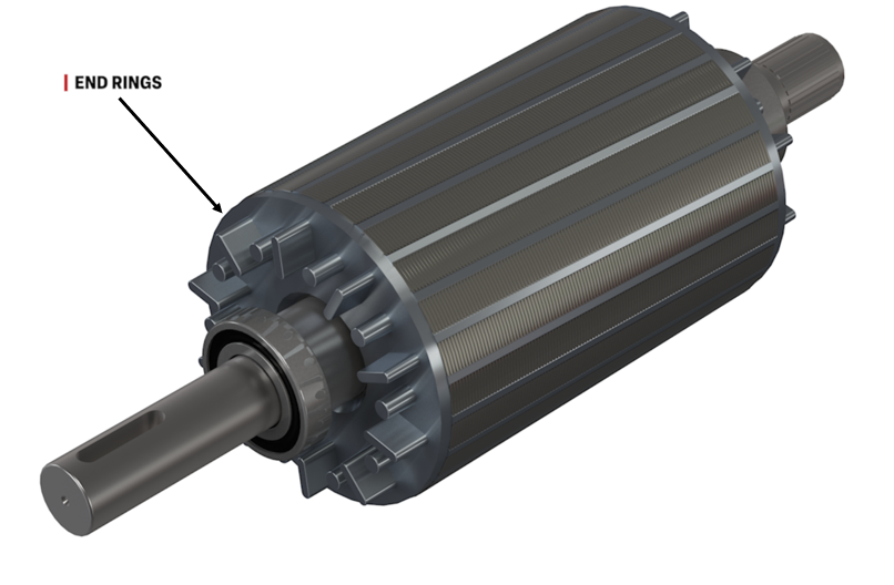
4. Machining and Laser Marking
Once the core of the rotor assembly is created, it is machined to remove excess materials from the end rings and, if needed, create external design features. Since some rotors run at more than 10,000 rpm, machining must be very precise to achieve very high mechanical tolerances with a computer numerical control (CNC) machine.
At this stage, the manufacture of the rotor core is complete. This is the ideal time in production to laser mark the lamination assembly (or squirrel cage). Data matrix codes (DMCs) or serial numbers are marked to gather production data and improve quality control.
In the following video, you can see the laser marking of a high temperature rotor.
5. Shaft Laser Cleaning and Press Fitting
The rotor shaft is now the only part missing. The shaft ensures an efficient mechanical transfer which brings power to the EV’s wheels. Manufactured separately, the shaft can be cleaned with a laser to remove oil, dust, or any contaminants remaining from its manufacturing. It can also be laser marked for traceability or tracking purposes.
In the following video, you can see the laser cleaning of the rotor shaft.
After cleaning, the shaft is inserted into the rotor’s core using a pneumatic press-fit machine. To perform a successful press fit, the hole in the center of the rotor’s core must be just a bit smaller than the shaft to ensure proper interference between the two parts to hold them in place. This is achieved by heating the rotor’s core a few seconds before press fitting. This process is usually automated.
In the following video, you can see the rotor shaft insertion.
6. Impregnation and Balancing
Now that the rotor is completely assembled, it is impregnated in a resin bath to improve its mechanical strength and protect it from external elements.
To sustain speeds as high as 10,000 rpms, precise balancing is required to ensure smooth running without vibration. Mass distribution is measured by placing the rotor on a horizontal or vertical fixture equipped with measuring devices such as accelerometers, tachymeters, and scales. These instruments monitor acceleration, rotation speed, and weight as the rotor spins. Adjustments are made until the balance is met.
In the following video, you can see the rotor’s balancing in detail.
The Path to Electric Motor Efficiency
The production process of a rotor involves many crucial steps and critical performance gains can be achieved during each of them. Smart design choices will lead to more efficient production and quality control near the end of manufacturing.
Using laser processes for traceability and surface preparation along the way will ensure continuous process improvement and maximize parts performance.
In a competitive automotive landscape, every gain in electric motors efficiency is a gain in speed, reliability, and energy saving. Using automation and a green technology like laser in the rotor manufacturing process is now essential to scale-up production and reduce the environmental footprint.
Technical expert and consultant in batteries and electrical propulsion systems, Stéphane holds a Physics degree with specializations in Photonics, Optics, Electronics, Robotics, and Acoustics. Invested in the EV transformation, he has designed industrial battery packs for electrical bikes. In his free time, he runs a YouTube channel on everything electrical.
In recent years, data centers have experienced unprecedented growth, mainly driven by the rapid expansion of artificial intelligence (AI). This surge comes with massive energy demands, with more centers being built, and computing workloads becoming far more energy intensive.
While lithium-ion batteries dominate the electric vehicle market, there are continuing concerns about shortages of raw materials, costs, and extraction and mining practices. Lithium production is expensive and it’s not particularly eco-friendly.
Lithium-ion batteries have been powering our devices and electric vehicles for years, but solid-state batteries are now heralded as the next big thing. But how accurate is that claim?