We have been saying for quite some time now that laser Direct Part Marking (DPM) is the sturdiest way to implement a traceability system. We have put our beliefs to the test, and the results are in. Watch our webcast highlighting the results of our real-life tests of the robustness of aluminum laser marking.
Sturdy Laser Direct Part Marking Resists Several Post Process Treatments
Industrial lasers can be used to etch information, such as company logos, model numbers and texts, barcodes and 2D barcodes on various materials. Our experiments were conducted with Data Matrix codes etched on aluminum with T4, T6, T7 heat treatment using CobaPressTM. We also tested chromate conversion, shot blasting and e-coating.
Let’s start by going over some of the concepts required to understand the experiment: Data Matrix Code, focal length, laser feed, line spacing and the number of passes. Then, we will present the actual results of the tests.
2D barcodes - The Data Matrix Code
The DMC can be read by digital scanners either by hand or with an automated system. DMCs are composed of black and white cells that seem to be arranged randomly, but don’t get fooled by appearances. The patterns are highly codified. The content of the code is duplicated so that, even if some of the code is erased or otherwise rendered illegible, there won’t be any lost information. Try that with traditional linear barcodes, which have no redundancy; information can easily be lost if the barcode becomes damaged.
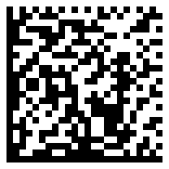
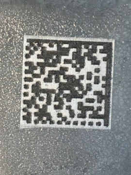
Typical Data Matrix Code
Two sides of the code are solid black. The two others alternate black and white. These are the only localization features of the DMC.
The background must extend beyond the code to create a quiet zone, a blank area that helps the scanner identify the end of the code.
The size of the code is commonly expressed in number of cells. This one has 24 by 24 cells and can hold up to 52 characters, It contains the message: https://www.laserax.com. That DMC can be etched (thanks to a high-resolution laser marker) on a 240 mm2 area (0.372 in2).
Two parameters are used to characterize the quality of the Data Matrix code. First, the contrast level is the difference of greyscale between the dark cells and pale cells.
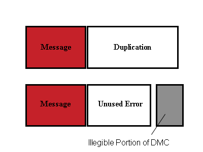
The information encoded in the Data Matrix code is duplicated. The duplication ensures that even if a portion of the DMC is damaged, the message will be protected. In the image below, the size of the duplication is compared to the size of the actual message.
When the DMC is damaged, the scanner is using a portion of the duplication to get the complete message. The unused error is the duplication that is remaining to compensate for even more damage to the DMC. We prefer large unused errors because it signals a better protection for the message.
Throughout this text we will discuss the best laser parameters for each post-process treatment studied. Several parameters affect the way the beam interacts with the material each need to be optimized to get the best marking results. Let’s define the most frequently used before getting in the thick of things.
Some Useful Laser Parameters
The focal length (FL) is related to the lens used. Lenses with a smaller FL converge faster; that means that the distance between the laser head and material will also need to be smaller. It might seem like a good thing; however, they also diverge faster, allowing only small variations in part positioning. Lenses with small FL tend to provide more intense beams.
The laser feed is the speed at which the laser beam sweeps the surface. Pulsed lasers are favored in most industrial applications. Since the elapsed time between the crest of each cycle is constant, the marking speed will have an important influence on the density of energy received by the material. Increasing the marking speed reduces the density of the energy delivered by the laser.
Line spacing is the distance between each sweep of the laser beam. Smaller line spacing will provide more energy per unit area to the material.
Number of passes along with marking speed and line spacing, the number of passes determine the total marking time. It is the best way to create a deep trench into the material.
Laser Direct Part Marking with Post Process Treatment
In the following webcast, we introduce the results of an experiment in which DMCs engraved in aluminum parts were subjected to heat treatments, shot blasting, e-coating, combined shot blasting and e-coating, and finally chromate conversion coating. Guess what? We have found solutions to make good on our promise that laser DPM withstands all of those post-process surface treatments.
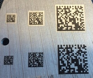
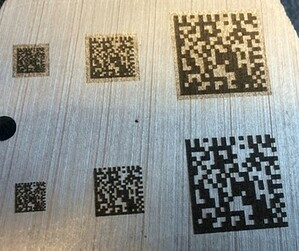
We submitted a DMC etched by laser on a A356 sample to T4, T6/7 regular heat treatment as well as to T4, T6 and T7 heat treatments using CobapressTM. The following pictures are shown in before and afters.
Heat Treatments (T4, T6 and T7)
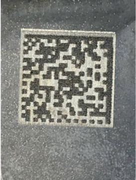
T4 Heat Treatment a) Before and b) After
The DMC etched on the part submitted to T4 (1 hour at 500 oC) had excellent legibility after the solution heat treatment, as can be seen in the pictures above.
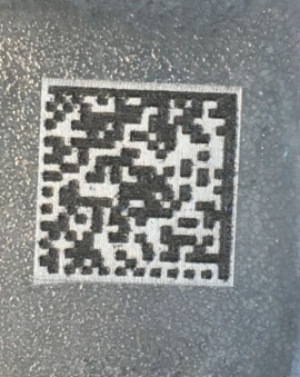
T6/7 Heat Treatment a) Before and b) After
The DMC etched on the part submitted to T6/7 (4 hours at 520 oC) had excellent legibility after the solution heat treatment, as shown in the pictures above.
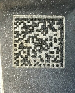
T4 CobaPressTM Heat Treatment a) Before and b) After
The DMC etched on the part submitted to CobapressTM T4 (1 hour at 500 oC) had excellent legibility after the heat treatment, as shown in the pictures above.
T6/7 CobaPressTM Heat Treatment a) Before and b) After
The DMC etched on the part submitted to Cobapress T6/7 (4 hours at 520 oC) also had excellent legibility after the treatment, as shown in the pictures above.
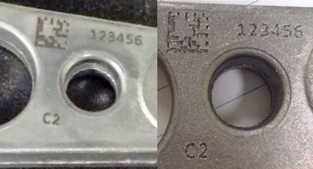
Chromate Conversion Coating
Often used to inhibit corrosion, as a primer or for other aesthetic purpose, chromate conversion is a mild surface treatment. However, it has its own challenges when it comes to laser DPM.
Chromate Conversion Coating a) Before and b) After
Best results are achieved using a DMC with a cell size of 0.3 mm, 0.5 mm and 1.0 mm. The background of the DMC should be left natural for better results.
Shot Blasting
Shot blasting is used in the die casting industry to remove flashes at the joint plan and achieve even surfaces throughout..
Regular Laser Marking does not Resist to Shot Blasting
Shot blasting is probably the most challenging surface treatment for DMCs engraved by laser—or by any other means for that matter. The regular laser markings did not pass the test. As shown below, the markings were badly damaged by the shot blasting and became illegible.
Shot Blasting with Regular Laser Direct Part Marking a) Before and b) After
Laserax’s Special Laser Direct Part Marking Resists Shot Blasting
In order to protect the markings from the shot medium, we have dug deeper into the material. To do so, we used a lens with smaller focal length and a large number of passes.
Trenches need to be adapted to the shot medium to protect the DMC
Our best results, under the specific conditions of the experiment, was achieved with a 0.6 mm cell size. 12 passes were required, The entire marking process took about 37 seconds for a 100 W fiber laser. It is of the utmost importance that the cell size be adapted to the shot medium and process optimization is required for your specific configurations, as shown in the image above. Contact a laser expert to see if your process can be studied in depth.
E-coating
Very similar to anodization, e-coating consists of dipping the part in a bath that contains organic paint. An electrical current flow is established and attract the paint to the metallic parts.
Our tests showed that cells smaller than 0.75 mm gives poor results. White backgrounds do not affect either positively or negatively the legibility of the marking after e-coating.
E-coating a) Before and b) After
Our best results were achieved with a cell size of 1.25 mm, marking speed of 600 mm/s, and line spacing of 0.175 mm. The best contrast achieved was 0.753 and unused error of 100. A DMC size of 20 mm took 2 seconds to mark with our 100 W laser.
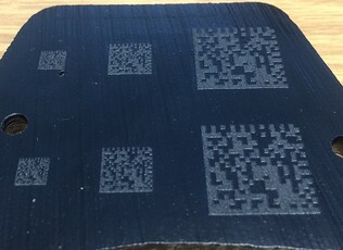
Shot Blasting and E coating
Finally, a DMC laser etched aluminum part was subjected to both shot blasting and e-coating. See results below.
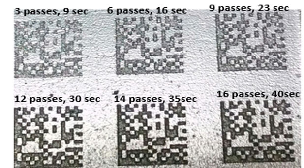
After shot blasting and e-coating for different number of passes
Our best results were achieved with deep marking without whitening the background. An individual cell size of 0.6 mm, code size of 13.2 mm and 12 passes generated total marking time of 37 seconds.
Conclusion
Laser direct part marking can be used even with the most challenging post-treatment processes. Your regular laser marking will resist to T4, T6 and T7 heat treatments.
A white background doesn’t influence or have a negative impact on the legibility of a DMC after chromate conversion coating and e-coating. The cells of the DMC for e-coating should be bigger than 0.75 mm.
With a large number of passes and cell sizes adapted to the shot medium, we were able to get adequate DMC even after shot blasting.
Under some circumstances, e-coating will improve the legibility of the DMC that was previously subjected to shot blasting using our adapted marking procedure.
Normand is a well-rounded and autonomous marketing professional with a recent specialization in web marketing. He thrives to share experiences, to apply knowledge, to learn new things and get stuff done.
When precision marking is required on delicate or heat-sensitive materials, ultraviolet (UV) laser technology offers a distinct advantage.
By minimizing thermal impact, UV laser marking creates high-contrast, permanent marks while preserving material integrity and meeting demanding traceability requirements.
Walk into any Hospital and you'll see it immediately. Every single tool, implant, and device has some kind of marking on it. Serial numbers, logos, barcodes. When you're putting something inside someone's body, or even just touching their skin, you need to know exactly what it is, where it came from, and when it was made.
In an industry shaped by strict regulations, globalized manufacturing, and increasing patient expectations, the ability to know exactly where a device has been, how it was made, and where it is going has become essential.